Cockroft-Walton
https://nomad-power-system.blogspot.com/2020/04/cockroft-walton.html
One of the cheapest and popular ways of generating high voltages at relatively low currents is the classic multistage diode/capacitor voltage multipler, known as Cockcroft Walton multiplier, named after the two men who used this circuit design to be the first to succeed in performing the first nuclear disintegration in 1932. James Douglas Cockcroft and Ernest Thomas Sinton Walton, in fact have used this voltage multiplier cascade for the research which later made them winners of the 1951 Nobel Prize in physics for "Transmutation of atomic nuclei by artificially accelerated atomic particles". Less known is the fact that the circuit was first discovered much earlier, in 1919, by Heinrich Greinacher, a Swiss physicist. For this reason, this doubler cascade is sometimes also referred to as the Greinacher multiplier.
Unlike transformers this method eliminates the requirement for the heavy core and the bulk of insulation/potting required. By using only capacitors and diodes, these voltage multipliers can step up relatively low voltages to extremely high values, while at the same time being far lighter and cheaper than transformers. The biggest advantage of such circuit is that the voltage across each stage of this cascade, is only equal to twice the peak input voltage, so it has the advantage of requiring relatively low cost components and being easy to insulate. One can also tap the output from any stage, like a multitapped transformer. They have various practical applications and find their way in laser systems, CRT tubes, hv power supplies, LCD backlighting, power supplies, x-ray systems, travelling wave tubes, ion pumps, electrostatic systems, air ionisers, particle accelerators, copy machines, scientific instrumentation, oscilloscopes, and many other applications that utilize high voltage DC.
Related: What is Free Energy?
Cockcroft Walton Circuit
The CW generator is a voltage multiplier that converts AC or pulsing DC electrical power from a low voltage level to a higher DC voltage level. It is made up of a voltage multiplier ladder network of capacitors and diodes to generate high voltages. Unlike transformers, this method eliminates the requirement for the heavy core and the bulk of insulation/potting required. Using only capacitors and diodes, these voltage multipliers can step up relatively low voltages to extremely high values, while at the same time being far lighter and cheaper than transformers. The biggest advantage of such circuits is that the voltage across each stage of the cascade is equal to only twice the peak input voltage in a half-wave rectifier. In a full-wave rectifier it is three times the input voltage. It has the advantage of requiring relatively low-cost components and being easy to insulate. One can also tap the output from any stage, like in a multitapped transformer.

To understand the circuit operation, see the diagram of the two-stage version at right. Assume the circuit is powered by an alternating voltage Vi with a peak value of Vp, and initially the capacitors are uncharged. After the input voltage is turned on
- When the input voltage Vi reaches its negative peak −Vp, current flows through diode D1 to charge capacitor C1 to a voltage of Vp.
- When Vi reverses polarity and reaches its positive peak +Vp, it adds to the capacitor's voltage to produce a voltage of 2Vp on C1s righthand plate. Since D1 is reverse-biased, current flows from C1 through diode D2, charging capacitor C2 to a voltage of 2Vp.
- When Vi reverses polarity again, current from C2 flows through diode D3, charging capacitor C3 also to a voltage of 2Vp.
- When Vi reverses polarity again, current from C3 flows through diode D4, charging capacitor C4 also to a voltage of 2Vp.
With each change in input polarity, current flows up the "stack" of capacitors through the diodes, until they are all charged. All the capacitors are charged to a voltage of 2Vp, except for C1, which is charged to Vp. The key to the voltage multiplication is that while the capacitors are charged in parallel, they are connected to the load in series. Since C2 and C4 are in series between the output and ground, the total output voltage (under no-load conditions) is Vo = 4Vp.
This circuit can be extended to any number of stages. The no-load output voltage is twice the peak input voltage multiplied by the number of stages N or equivalently the peak-to-peak input voltage swing (Vpp) times the number of stages

The number of stages is equal to the number of capacitors in series between the output and ground.
 | |
| A three-stage full-wave CW multiplier |
One way to look at the circuit is that it functions as a charge "pump", pumping electric charge in one direction, up the stack of capacitors. The CW circuit, along with other similar capacitor circuits, is often called charge pump. For substantial loads, the charge on the capacitors is partially depleted, and the output voltage drops according to the output current divided by the capacitance.
Half-Wave Voltage Doubler
The half-wave voltage doubler in Figure below (a) is composed of two circuits: a clamper at (b) and peak detector (half-wave rectifier) in Figure prior, which is shown in modified form in Figure below (c). C2 has been added to a peak detector (half-wave rectifier).
Half-wave voltage doubler (a) is composed of (b) a clamper and (c) a half-wave rectifier.
Half-wave Voltage Doubler Operation Circuit Analysis
Referring to Figure(b) above , C2 charges to 5 V (4.3 V considering the diode drop) on the negative half cycle of AC input. The right end is grounded by the conducting D2. The left end is charged at the negative peak of the AC input. This is the operation of the clamper.
During the positive half cycle, the half-wave rectifier comes into play at Figure(c) above . Diode D2 is out of the circuit since it is reverse biased. C2 is now in series with the voltage source. Note the polarities of the generator and C2, series aiding. Thus, rectifier D1 sees a total of 10 V at the peak of the sinewave, 5 V from generator and 5 V from C2. D1 conducts waveform v(1) (figure below), charging C1 to the peak of the sine wave riding on 5 V DC (figure below v(2)). Waveform v(2) is the output of the doubler, which stabilizes at 10 V (8.6 V with diode drops) after a few cycles of sine wave input.
 | *SPICE 03255.eps C1 2 0 1000p D1 1 2 diode C2 4 1 1000p D2 0 1 diode V1 4 0 SIN(0 5 1k) .model diode d .tran 0.01m 5m .end
|
Voltage doubler: v(4) input. v(1) clamper stage. v(2) half-wave rectifier stage, which is the doubler output.
Full-Wave Voltage Doubler
The full-wave voltage doubler is composed of a pair of series stacked half-wave rectifiers. (Figure below) The corresponding netlist is in Figure below.
Full-Wave Voltage Doubler Operation Analysis
The bottom rectifier charges C1 on the negative half cycle of input. The top rectifier charges C2 on the positive halfcycle. Each capacitor takes on a charge of 5 V (4.3 V considering diode drop). The output at node 5 is the series total of C1 + C2 or 10 V (8.6 V with diode drops).
 | *SPICE 03273.eps *R1 3 0 100k *R2 5 3 100k D1 0 2 diode D2 2 5 diode C1 3 0 1000p C2 5 3 1000p V1 2 3 SIN(0 5 1k) .model diode d .tran 0.01m 5m .end
|
Full-wave voltage doubler consists of two half-wave rectifiers operating on alternating polarities.
Note that the output v(5) Figure below reaches full value within one cycle of the input v(2) excursion.
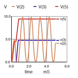
Full-wave voltage doubler: v(2) input, v(3)voltage at mid point, v(5) voltage at output
Deriving Full-wave Doublers from Half-wave Rectifiers
Figure below illustrates the derivation of the full-wave doubler from a pair of opposite polarity half-wave rectifiers (a). The negative rectifier of the pair is redrawn for clarity (b). Both are combined at (c) sharing the same ground. At (d) the negative rectifier is re-wired to share one voltage source with the positive rectifier. This yields a ±5 V (4.3 V with diode drop) power supply; though, 10 V is measurable between the two outputs. The ground reference point is moved so that +10 V is available with respect to ground.

Full-wave doubler: (a) Pair of doublers, (b) redrawn, (c) sharing the ground, (d) share the same voltage source. (e) move the ground point.
Cockcroft-Walton Multiplier
A voltage multiplier of cascaded half-wave doublers of arbitrary length is known as a Cockcroft-Walton multiplier as shown in Figure below. This multiplier is used when a high voltage at low current is required. The advantage over a conventional supply is that an expensive high voltage transformer is not required– at least not as high as the output.

Cockcroft-Walton x8 voltage multiplier; output at v(8).
The pair of diodes and capacitors to the left of nodes 1 and 2 in Figure above constitute a half-wave doubler. Rotating the diodes by 45o counterclockwise, and the bottom capacitor by 90o makes it look like Figure prior (a). Four of the doubler sections are cascaded to the right for a theoretical x8 multiplication factor. Node 1 has a clamper waveform (not shown), a sinewave shifted up by 1x (5 V). The other odd numbered nodes are sinewaves clamped to successively higher voltages. Node 2, the output of the first doubler, is a 2x DC voltage v(2) in Figure below. Successive even numbered nodes charge to successively higher voltages: v(4), v(6), v(8)
 | D1 7 8 diode C1 8 6 1000p D2 6 7 diode C2 5 7 1000p D3 5 6 diode C3 4 6 1000p D4 4 5 diode C4 3 5 1000p D5 3 4 diode C5 2 4 1000p D6 2 3 diode D7 1 2 diode C6 1 3 1000p C7 2 0 1000p C8 99 1 1000p D8 0 1 diode V1 99 0 SIN(0 5 1k) .model diode d .tran 0.01m 50m .end
|
Cockcroft-Walton (x8) waveforms. Output is v(8).
Without diode drops, each doubler yields 2Vin or 10 V, considering two diode drops (10-1.4)=8.6 V is realistic. For a total of 4 doublers one expects 4·8.6=34.4 V out of 40 V.
Consulting Figure above, v(2) is about right; however, v(8) is <30 V instead of the anticipated 34.4 V. The bane of the Cockcroft-Walton multiplier is that each additional stage adds less than the previous stage. Thus, a practical limit to the number of stages exist. It is possible to overcome this limitation with a modification to the basic circuit. [ABR] Also note the time scale of 40 msec compared with 5 ms for previous circuits. It required 40 msec for the voltages to rise to a terminal value for this circuit. The netlist in Figure above has a “.tran 0.010m 50m” command to extend the simulation time to 50 msec; though, only 40 msec is plotted.
The Cockcroft-Walton multiplier serves as a more efficient high voltage source for photomultiplier tubes requiring up to 2000 V. [ABR] Moreover, the tube has numerous dynodes, terminals requiring connection to the lower voltage “even numbered” nodes. The series string of multiplier taps replaces a heat generating resistive voltage divider of previous designs.
An AC line operated Cockcroft-Walton multiplier provides high voltage to “ion generators” for neutralizing electrostatic charge and for air purifiers.
Cockroft Walton DC Generator
Voltage Multiplier Review:
- A voltage multiplier produces a DC multiple (2,3,4, etc) of the AC peak input voltage.
- The most basic multiplier is a half-wave doubler.
- The full-wave double is a superior circuit as a doubler.
- A tripler is a half-wave doubler and a conventional rectifier stage (peak detector).
- A quadrupler is a pair of half-wave doublers
- A long string of half-wave doublers is known as a Cockcroft-Walton multiplier.
Cockroft Walton Accelerator
The Cockcroft–Walton (CW) generator, or multiplier, is an electric circuit that generates a high DC voltage from a low-voltage AC or pulsing DC input.
This Cockcroft–Walton voltage multiplier was part of one of the early particle accelerators responsible for development of the atomic bomb. Built in 1937 by Philips of Eindhoven it is now in the National Science Museum in London, England.

The Cockcroft Walton accelerator performed the first nuclear disintegration by artificial means. Cockcroft and Walton accelerated protons up to voltage of 700kV and bombarded them onto a target of lithium producing the reaction:
11P + 73Li -> 42He + 42He
This was the first experiment to show that one element (lithium) could be artificially transformed or transmuted into another element (helium).
The Cockcroft–Walton accelerator is a multiplier. To obtain more than about 200 kV of accelerating voltage, it is necessary to use one or more stages of voltage-doubling circuits. The first such device was built by J. D. Cockcroft and E. T. S. Walton in 1932 and was used for the first transmutation experiments with artificially accelerated particles (protons).
Cockcroft-Walton accelerators are still widely used today, sometimes as injectors to much larger accelerators.
Cockroft And Walton E = mc²
This experiment by John Cockcroft and Ernest Walton is famous for being the first nuclear transmutation by artificially accelerated particles, as opposed to mere observations of natural radioactive decay.[1] Such particle accelerators were called "atom smashers" at the time.
Conducted in April 1932 at the University of Cambridge's Cavendish Laboratory in England, the physicists Cockroft and Walton successfully split lithium nuclei by colliding them with artificially accelerated protons. Cockroft and Walton were honored with the Nobel Prize in 1951 for this.[2]
Cockcroft and Walton "did not see their experiments as a "test" or "proof" of Einstein's mass-energy relationship; that was not the goal of the experiment. Rather, they simply used that relationship in their analysis, assuming it to be valid."[3] The E=mc² equation had in fact been proposed, and analyzed for nuclear decays, more than 20 years earlier. The scope of this experiment was too narrow to purport to verify the equation in the general case. See Experimental and Observational Evidence Confirming Relativity for a discussion of this point.
As explained by Stanford Encyclopedia of Philosophy:[4]
| “ | As Stuewer (1993) has suggested, Cockcroft and Walton use mass-energy equivalence to confirm their hypothesis about what happens when 7Li is bombarded by protons. Hence, it does not seem we ought to regard this experiment as a confirmation of E=mc². However, if we take some of the other evidence that Cockcroft and Walton provide concerning the identification of the products in reaction p + 7Li → α + α as sufficient to establish that the products are indeed α-particles, then we can interpret this experiment as a confirmation of mass-energy equivalence, which is how this experiment is often reported in the physics literature. | ” |
Others have asserted that Cockcroft and Walton did discover some kind of confirmation of the E=mc² equation, such as physicist Kenneth Bainbridge in 1933:
The gain in energy in the reaction is 16.97×10⁶ e-volts, an energy equivalent to 0.0182 mass units on the O16 scale if ΔE =C²Δm. Taking Aston's values for the mass of helium and hydrogen and the author's value, 7.0146±0.0006 for Li7, the mass change is 0.0181 ± 0.0006 in the reaction which may be represented as Li7 + p → 2α. Within the probable error of the measurements the equivalence of mass and energy is satisfied. --Kenneth Bainbridge
Nevertheless, this experiment is often championed by physicists as being confirmation of Albert Einstein's famous formula E=mc². It is not a good "proof" of the formula; it was too specific to make such a sweeping claim. It was simply consistent with the formula, and that consistency was noted at the time and continues to be noted.[5][6
✩ ✩ ✩ ✩ ✩ ✰* Revealed At Last: Ancient Invention Generates Energy-On-Demand
✔ Nikola Tesla’s method of magnifying electric power by neutralizing the magnetic counter-forces in an electric generator
✔ Principle of Resonance to achieve Overunity
✔ Generate generators without rotating motion, but based on the principle of rotating magnets. Because magnetism varies based on electronic circuit design: coils, capacitors, Negative resistance, etc.The change of magnetism does not require the rotation of the magnet.
Generates Energy-On-Demand: Easy Power Plan Will Change Our World Forever
✔ Currents are 180 out of phase with each other, Lenz's law naturally is broken✔ Principle of Resonance to achieve Overunity
✔ Generate generators without rotating motion, but based on the principle of rotating magnets. Because magnetism varies based on electronic circuit design: coils, capacitors, Negative resistance, etc.The change of magnetism does not require the rotation of the magnet.
You and your family will always be protected and constantly having enough green energy for cooking and preserving your food…NO LONGER at the mercy of FEMA and the Government.

- ↑ Mike Poole Cockcroft's subatomic legacy: splitting the atom, Cern Courier, Nov 20, 2007
- ↑ The Nobel Prize in Physics 1951, Nobelprize.org, 23 Jan 2013
- ↑ Roger H. Stuewer: Mass-Energy in Einstein in Context, Cambridge University Press
- ↑ Fernflores, Francisco, "The Equivalence of Mass and Energy," The Stanford Encyclopedia of Philosophy (Spring 2012 Edition), Edward N. Zalta (ed.)
- ↑ The Center for History of Physics: Einstein: Image and Impact, © 1996-2004 - American Institute of Physics
- ↑ Louise Boylan: Cockroft and Walton Experiment: Converting Mass into Energy


I really appreciate for such an nice information about cockroft dc generators check it out wyze discount code 2022
ReplyDelete